Resistors are the most fundamental and basic electronic components. Even though they are simple, they are essential for every circuit. Their primary job is to “resist” or control the flow of electrical current using specific conductive materials.
Resistors can also be connected together in various series and parallel combinations to perform several tasks:
- Voltage Dividers: Reducing the voltage to a specific level.
- Current Limiters: Protecting sensitive components from high current.
A resistor is a “Passive Device.” This means it does not create or amplify energy. Instead, it reduces the voltage or current passing through it. During this process, electrical energy is converted into heat. To make current flow, there must be a voltage drop across the resistor’s terminals to balance this energy loss.
Ohm’s Law
Ohm’s law states that the voltage across a conductor is directly proportional to the current flowing through it, provided all physical conditions and temperatures remain constant.
Mathematically, this current-voltage relationship is written as,
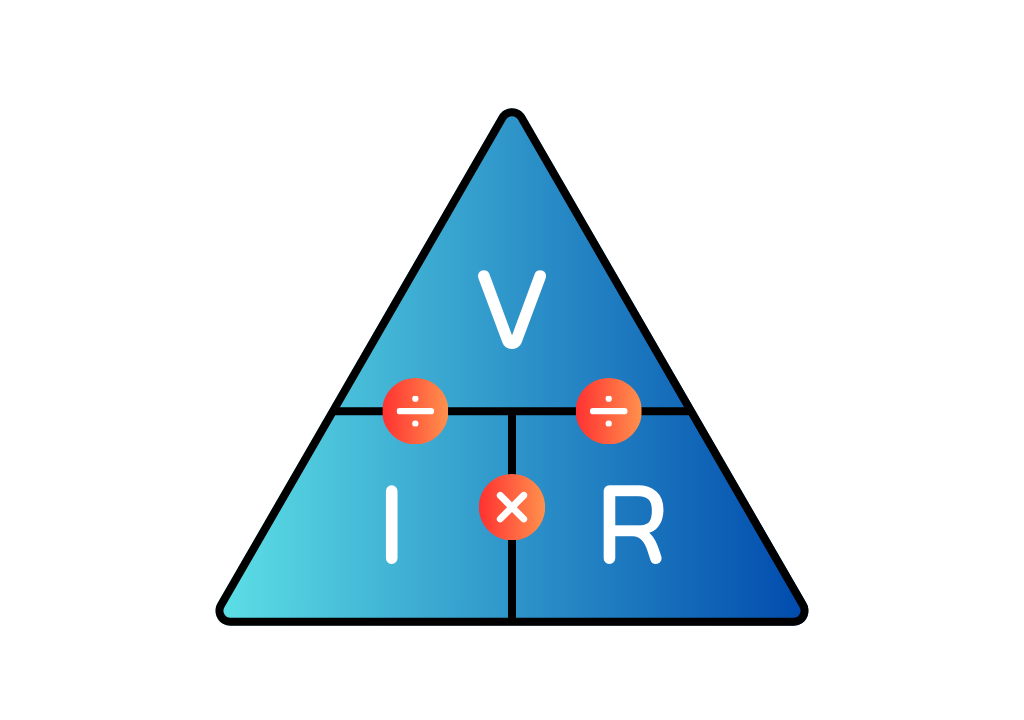
$$V = I \times R$$
V: is the voltage across the conductor (V).
I: is the current flowing through the conductor (A).
R: is the resistance provided by the conductor to the flow of current (Ohm).
A simple way to remember how to calculate any of the three values is to use the triangle method. You cover the value you want to find, and the remaining letters show you the formula.
Ohm’s Law Applications
The main applications of Ohm’s law are:
- Circuit Analysis: To calculate the exact values of Voltage, Current, or Resistance.
- Voltage Control: To design circuits that maintain the correct voltage drop for specific components.
- Measuring Tools: It is used in designing DC ammeters and shunts to safely divert and measure current.
Limitations of Ohm’s Law
Following are the limitations of Ohm’s law:
- Unilateral Elements: It does not apply to components like diodes and transistors. These devices allow current to flow in only one direction, so the relationship between voltage and current is not constant.
- Non-Linear Elements: For components where resistance changes over time or due to other factors (like capacitance), the ratio of voltage to current is not stable.
- Temperature Changes: Since resistance often changes with heat, Ohm’s Law may not be accurate if the component gets too hot.
Any arrangement of resistors, whether connected in series, parallel, or in a complex network, can be reduced to a single equivalent resistance. Regardless of the network’s complexity, the behavior of all resistive elements is governed by the same fundamental principles, namely Ohm’s Law and Kirchhoff’s Circuit Laws.
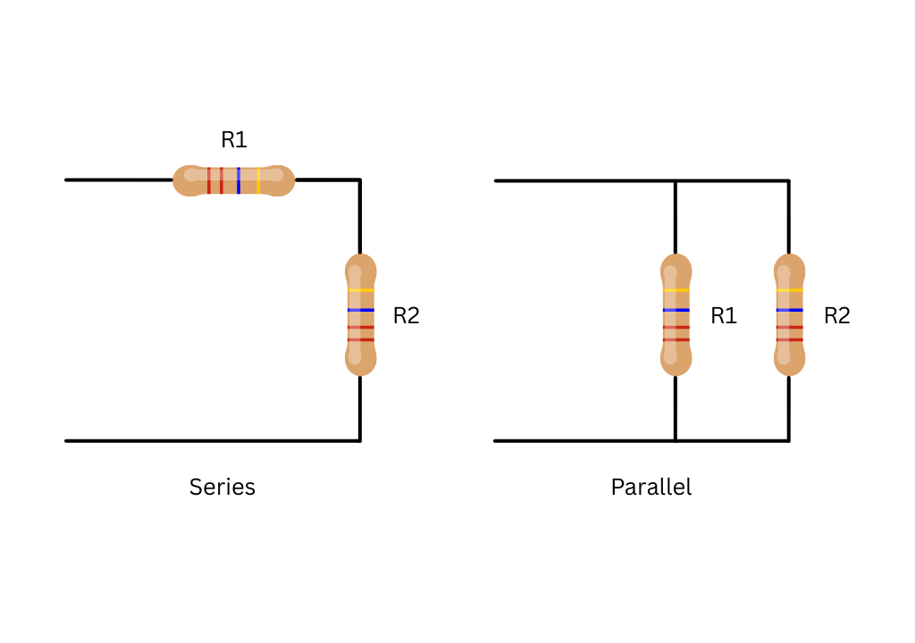
Resistors in Series
Resistors are in series when they are connected one after another in a single line. Because there is only one way for the current to go, the same amount of current must flow through every resistor.
Therefore, when resistors are connected in series, they all carry the same current. Since there is only one path for the current to flow, the current passing through one resistor must pass through all the others. Consequently, the current is identical at every point in a series resistor network.
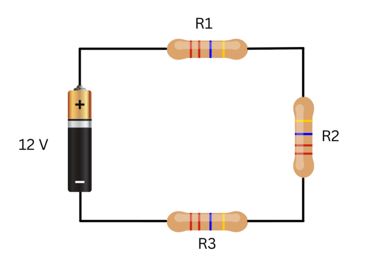
For a series connection:
$$I_{eq} = I_1 = I_2 = I_3$$
$$R_{eq} = R_1 + R_2 +R_3$$
Key Features to Remember:
- One Path: There are no branches. The electricity flows in a single loop from start to finish.
- Identical Current: The current (I) is exactly the same at every point in the circuit.
- Total Resistance: To find the total resistance, you simply add them all together.
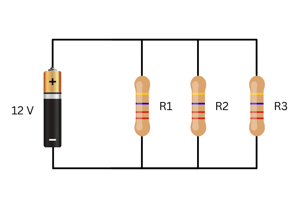
Resistors in Parallel
Resistors are considered to be connected in parallel when the terminals of each resistor are connected to the same two nodes, so that all resistors share the same voltage across them.
Unlike a series resistor circuit, a parallel resistor network provides more than one path for the current to flow. For this reason, parallel circuits are described as current dividers.
Because the supply current can split among multiple paths, the current through each branch of a parallel network is not necessarily the same. However, the voltage drop across each resistor in a parallel resistive network is the same. Therefore, all resistors connected in parallel share a common voltage.
A parallel resistive circuit can thus be defined as one in which resistors are connected between the same two nodes. Such a circuit is characterized by having multiple current paths supplied by a common voltage source.
In a parallel resistor network, the voltage across resistor is equal to the voltage across and , and all are equal to the supply voltage.
For a parallel connection:
$$V_{eq} = V_1 = V_2 = V_3$$
\[
\frac{1}{R_{eq}} = \frac{1}{R_1} + \frac{1}{R_2} + \frac{1}{R_3}
\]
Key Features to Remember:
Multiple Paths: The circuit has branches. The current can flow through more than one path.
Common Voltage: The voltage (V) is the same across all resistors in the circuit.
Divided Current: The total current splits among the branches depending on their resistance.
Total Resistance: The equivalent resistance is found by adding the reciprocals of the individual resistances.
Conclusion
Resistors are one of the most essential components in electrical and electronic circuits. Though simple in construction, they play a crucial role in controlling current, dividing voltages, and protecting other components in a system. At the heart of resistor behavior is Ohm’s Law, which defines the fundamental relationship between voltage, current, and resistance.
Whether arranged in series or parallel, resistors affect how current flows and how voltage is distributed within a circuit — knowledge that is foundational for analyzing and designing both basic and advanced electrical systems. Understanding these principles equips you with the skills needed to tackle more complex circuit analysis in future topics.