Ladder diagram programming is very similar to how electrical push-buttons work. Since the logic is nearly identical, we will first look at how electricity flows through a simple push-button circuit. Then, we can apply that knowledge to ladder diagram programming.
There are two types of push-buttons:
Normally Open (NO): In its normal (unpressed) state, the contacts are separated, and no current flows. When pressed, the contacts connect and allow the current to flow.
Normally Closed (NC): In its normal (unpressed) state, the contacts are connected, allowing current to flow continuously. When pressed, the contacts separate and stop the current.
Now that we have learned about the operating principle of push-buttons, let’s apply that knowledge to Ladder Diagram programming.
Push Button (Physical): Requires a physical action (pressing) to change the electrical state of its contacts.
Ladder Diagram Contact (Logical): Requires a logical signal (a bit changing from 0 to 1) to change its state within the program’s execution.
That is the main difference between them.
In Ladder Diagram also have two types of contactors:
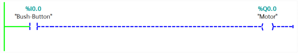
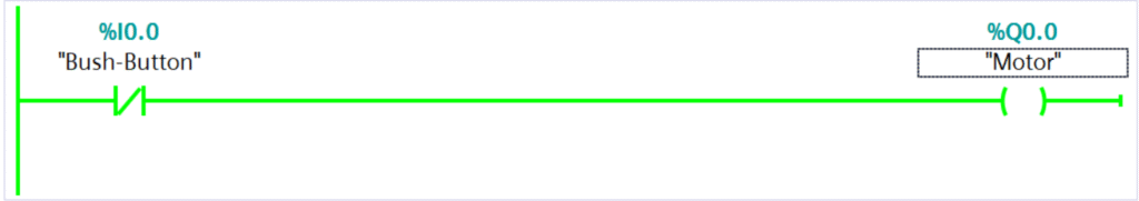
Normally Open Contact (NO): In its normal state, the contact remains open until it receives a signal. When it receives a signal, it closes, and the motor will turn on.
Normally Closed Contact (NC): In its normal state, the contact remains closed until it receives a signal. When it receives a signal, it opens, and the motor will stop.
Conditional Logic
In this example the conditions could be realized by a hard wire solution.
A machine turns on if start switch is pressed and EMG Switch and stop switches are unpressed.
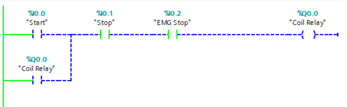
when you press Start, the Coil Relay energizes. This immediately closes the Auxiliary Contact. Now, even when you release the Start button, the electricity has a path through the closed auxiliary contact, keeping the relay energized (latched on) until either the Stop or EMG Stop button is pressed.
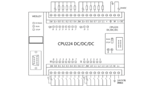
PLC Wiring Diagram
To realize the conditional logic statement from electrical circuit using ladder logic we connect the switches to a PLC as shown in Figure here.
So, the external control devices, such as the “Start,” “Stop,” and “EMG Stop” push-buttons, are wired to the input module of a Programmable Logic Controller (PLC). sending a voltage signal (in this case, 24V) to its input terminal, such as IN0, IN1, or IN2. The PLC continuously monitors these terminals and detects this incoming signal as a change in the input’s state from 0 to 1.
For our example, the code might be written to check if start switch is pressed and EMG Switch and stop switches are unpressed.
Based on the logical conditions defined in the program, the PLC makes a decision and updates the state of its output terminals. If the program’s conditions are met, the PLC will energize a specific output, such as OUT0. This action sends a voltage signal from the output module to an external component, like the Coil Relay. This energizes the relay, causing it to switch its contacts and control the power to a machine or another part of the system, effectively turning it ON or OFF as intended by the logic.
Read more about Programmable Logic Control (PLC)
- The Start push-button is a physical normally open (NO) device, so when you press the button, its contact closes, energizing input (%I0.0), the logical NO contact in the Ladder Diagram evaluates as True (ON), allowing the logic circuit to run.
- The Stop and EMG push-buttons are physical Normally Closed (NC) devices, so they constantly energize their inputs (%I0.1, %I0.2) in the normal state. Because the inputs are ON, the logical NO contacts in the Ladder Diagram evaluate as TRUE, allowing the circuit to run. When you press a physical Stop or EMG button, it opens, breaking the physical circuit. This de-energizes the corresponding input. The logical NO contact now evaluates as FALSE (open), which breaks the logic run.
Conclusion
Ladder diagram programming provides a logical method for controlling machinery. It uses Normally Open (NO) and Normally Closed (NC) contacts as logical representations of physical inputs like push-buttons. In a typical application, external control devices such as “Start” and “Stop” buttons are wired to a PLC’s input module. The PLC continuously reads the state of these inputs and processes them according to the conditional logic defined in the ladder program. If the programmed conditions are met, the PLC energizes an output terminal, which in turn activates an external component like a relay to control the machine’s operation. This process effectively translates physical actions into a logical sequence to automate and control industrial systems.